02. Quadrotor Kinematic and Dynamic Model 1
Quadrotor Kinematic and Dynamic Model
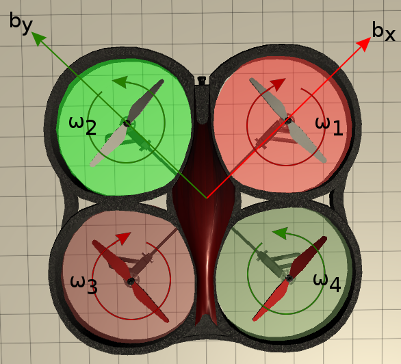
When discussing quadrotors, it is helpful to explicitly define two reference frames: a fixed world frame, {W}, and a moving body frame, {B}, that is rigidly attached to the quadrotor’s center of mass (CoM). Let’s assume that the x-axis of {B} points to motor number 1, the y-axis points to motor number 2, and the z-axis points “up” when the quadrotor is at rest on a level surface.
![F_i = thrust from motor _i_, (Newtons) and M_i = torque (moment) from propeller _i_ on {B}, (Newton*meters) where _i_ ∈ [1, 2, 3, 4]](img/quadrotor-annotated-2-pinta.png)
F_i = thrust from motor i, (Newtons) and M_i = torque (moment) from propeller i on {B}, (Newton*meters) where i ∈ [1, 2, 3, 4]
As you saw in the kinematics lessons, the orientation of the moving frame {B} can be described relative to {W} by using three Euler-angles. Specifically, let’s define the roll (\phi), pitch (\theta), and yaw (\psi) angles as an intrinsic (Z-X-Y) sequence of rotations, where,
In other words, left-multiplying a vector, p, expressed in {B} by {}^{W}_BR would give the coordinates of p expressed in {W},
Quadrotors have a number of features that make them interesting to study in the context of dynamics and controls. As previously mentioned, a rigid body in 3D space has six degrees of freedom. However, a quadrotor only has four motors to act as control inputs, thus a quadrotor is an example of an underactuated system. What this means is that a quadrotor cannot independently control each translational and rotational degree of freedom.
The underactuated nature of the quadrotor forces a kinematic coupling between some of the rotational and translational movements. In order for the quadrotor to move forward or backward, where \bold{b_x} denotes the “forward” direction, the quadrotor must have a positive pitch angle about the \bold{b_y} axis. Similarly, in order to move “right”, i.e., in the direction of the - \bold{b_y} axis, the quadrotor must have a positive roll angle about \bold{b_x}.
Movement in the vertical direction is conceptually much simpler. Each motor produces a force along the \bold{b_z} axis that is proportional to the motor’s angular speed squared,

where, k_F is a constant and i ∈ [1, 2, 3, 4]. The force of each motor is directed along the \bold{b_z}. If the net motor thrust is greater than the force of gravity, then quadrotor will accelerate “upwards”. Of course, the converse is also true.
Yawing motions - rotations about the \bold{b_z} - are slightly trickier. Motors located on the \bold{b_x} axis, motors 1 and 3, rotate clockwise (about the - \bold{b_z} axis), while the motors located on the \bold{b_y} axis, motors 2 and 4, rotate counter-clockwise. The opposing rotational pairs are necessary to negate the induced torques from the rotating blades on the body of the quadrotor. The magnitude of each rotor torque is proportional to the square of the motor’s angular speed,

where, k_M is a constant and i ∈ [1, 2, 3, 4].
By Newton’s Third Law, the torque produced on the quadrotor is opposite the direction of spin of the propeller. For the quadrotor in the Unity simulator (below), motors 1 and 3 lie on the \bold{b_x} axis and rotate in a clockwise direction (as viewed from above) while motors 2 and 4 lie on the \bold{b_y} axis and rotate counter-clockwise. Thus, the torque from motors 1 and 3 act in the + \bold{b_z} direction while the torque from motors 2 and 4 act in the - \bold{b_z} direction.
Note that in order to perform a pure yawing motion, i.e., rotate without changing elevation, one pair of motors would have to increase their angular speeds by the same amount as the opposite pair would have to decrease theirs.